Asynchronous Clock Domain Crossing: Part 2
When you have identified the CDC paths in your design using the techniques in Part 1, you then need to fix them..and there is something that you must understand right from the start ‐ You cannot solve CDC issues by timing constraints alone. Just using false paths or asynchronous clock groups, without and synchronizing circuits, will make all your inter-clock timing errors disappear, but all you are doing is hiding the underlying problem. You will also override any clock-crossing constraints inside Xilinx IPs such as FIFOs and AXI Interconnect.
Xilinx CDC library
Xilinx provides a a series of CDC synchronizer circuits as part of their Xilinx Parameterized Macro (XPM) libraries. Details of each macro can be found in the Libraries Guide for each device family (for example, UG974 for the UltraScale family).Selecting the correct CDC macro is vitally important – refer to UG949, the Ultrafast Design Methodology Guide, which shows the correct way of selecting single-bit and multi-bit CDC macros:
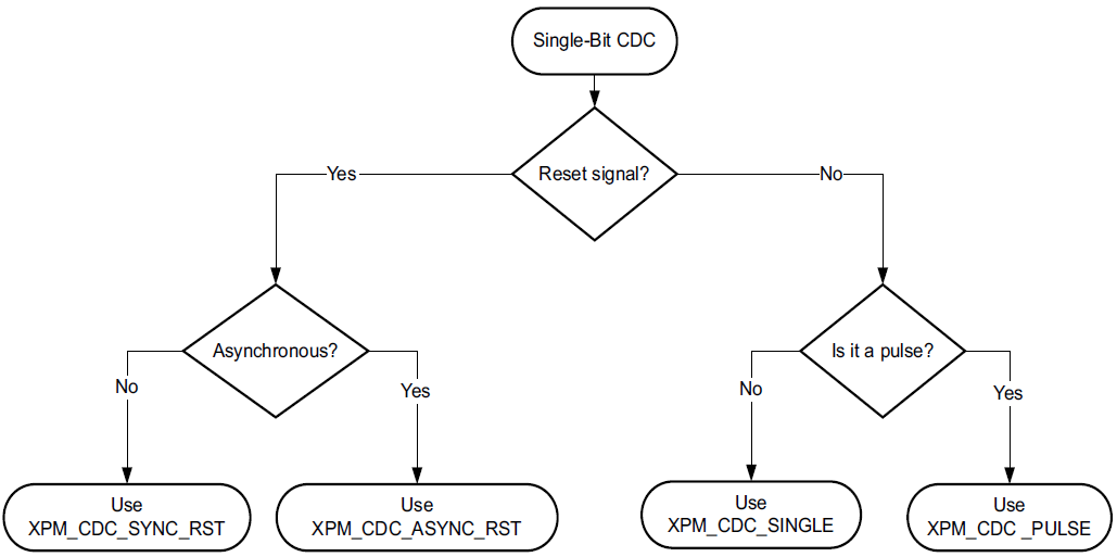
Figure 1: Single-bit CDC selection (copyright Xilinx)
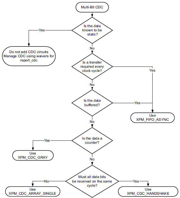
Figure 2: Multi-bit CDC selection (copyright Xilinx)
The CDC macros contain not only the hardware to safely pass from one clock domain to another, but also the necessary timing exception constraints to avoid errors during the Static Timing Analysis.
A Simple CDC Example
Lets look at a simple, if somewhat artificial, example of a 16bit counter that runs from a 50MHz clock domain and a comparator which flags when the counter equals 4 and runs from a 33MHz clock domain:
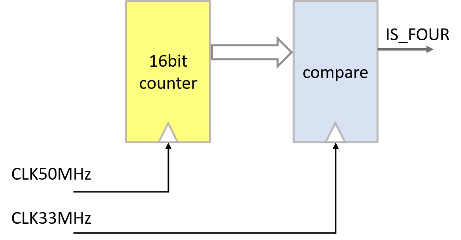
Figure 3: Simple Multi-bit CDC example
The appropriate constraints for the clocks are :
- create_clock -period 20.000 -name CLK50MHz [get_ports CLK50MHz]
- create_clock -period 30.303 -name CLK33MHz [get_ports CLK33MHz]
If we implement this design {code can be downloaded here}, Vivado will flag a timing error :

Figure 4: Simple Multi-bit CDC example – timing error
We can quite clearly see that the timing error is for an Inter-Clock path with different source and destination clocks and that the ‘Exception’
column is blank, indicating that no timing exception constraint exists for the failing path. At this point, we should already be alert to the possibility
of an uncontrolled CDC path in our design which we can confirm by running Vivado commands such as report_cdc and report_clock_interaction
as shown in part 1 :
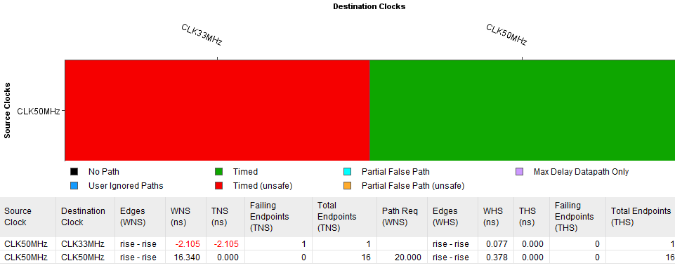
Figure 5: Report Clock Interaction shows unsafe paths
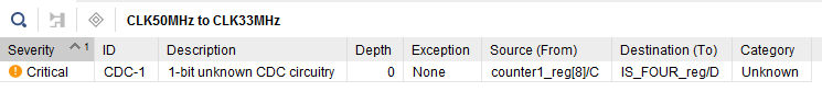
Figure 6: Report CDC shows uncontrolled clock-cross paths
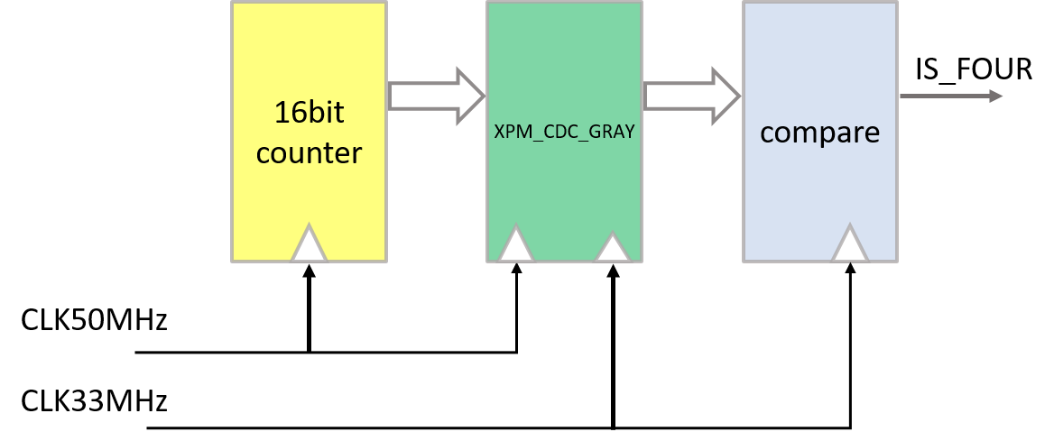
Figure 7: Simple Multi-bit CDC example – XPM_CDC_GRAY
We can now proceed to select a CDC synchronizer from the XPM library. The counter is 16bits wide, so we require a multi-bit synchronizer. Referring back to figure 2, we can see that one possible choice is the XPM_CDC_GRAY synchronizer. To include this in our design, we must instantiate it from the XPM library and insert it in the data path between counter and comparator ‐ {code can be downloaded here}.
Once we have the XPM_CDC_GRAY macro in our design, we can check it again with the Report Clock Interaction and Report CDC Vivado commands:
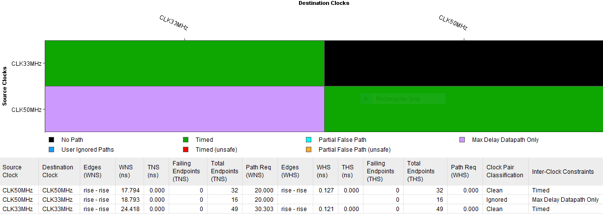
Figure 8: Report Clock Interaction shows all paths safe

Figure 9: Report CDC shows all CDC paths are controlled