Asynchronous Clock Domain Crossing: Part 1
Designing FPGAs which use a single clock domain is a luxury that very few of us have. Modern FPGA designs must cope with multiple clocks of different frequencies, very often
asynchronous to each other, and still be expected to work reliably.
Any flip-flop can be made to go metastable – just clock it such that its setup and/or hold time requirements are not met and sooner or later you will run into problems. Clock
domain crossing (CDC) paths are particularly prone to these problems as the asynchronous nature of the two clocks will guarantee that the receiving clock domain will run into
setup/hold violations. CDC issues will show up in your design as erratic, random behaviour which can be extremely difficult to track down. It is made even more difficult by the
fact that the “weird” behaviour will seemingly change with a number of different factors:
- At every power-on.
- The asynchronous clocks will have different phase differences from one power cycle to the next and so you’ll see different behaviour each time.
- Temperature.
- Fluctuations in temperature will change on-chip timing and hence the CDC paths.
- From device to device.
- Every device has slightly different internal delays, so their CDC paths will behave differently.
- From implementation to implementation.
- Uncontrolled CDC paths will be implemented differently each time, so seeming unrelated design changes can cause the CDC effects to either manifest themselves or disappear completely..
As a simple example of the dangers of crossing asynchronous clock domains, let’s look at a counter which is incremented by one clock and then sampled by a different, asynchronous clock.
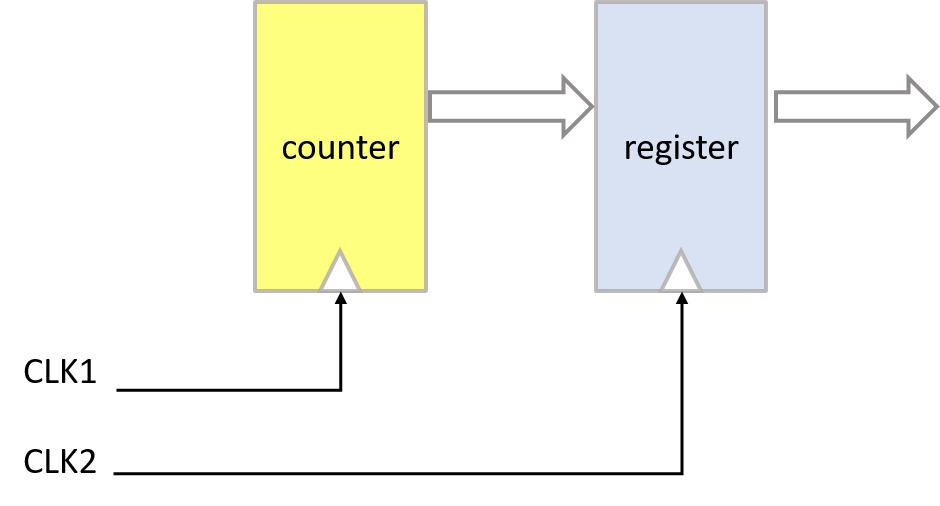
Figure 1: Clock crossing example
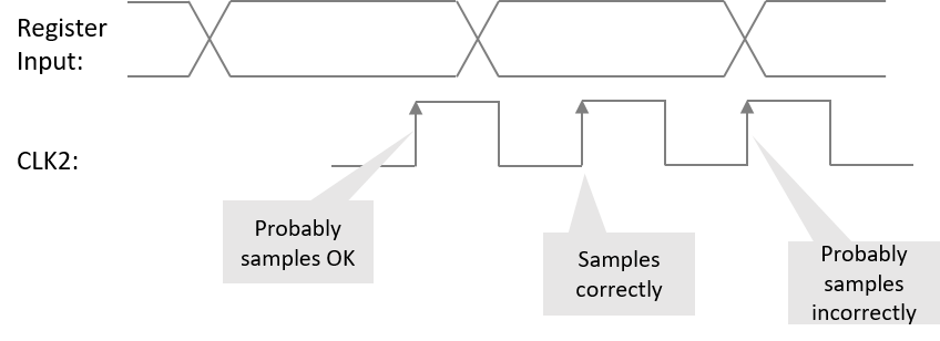
Figure 2: Sampling error due to CDC
So, what will we see at the register outputs? Well, most of the time, we will get the correct value as the counter bits are sampled when they are stable. But every so often,
the second clock will sample the counter bits when they are changing and not stable − this may or may not cause metastability, but we can be pretty certain that the register
outputs will not be the same as the counter value we hoped to see.
Finding CDC Paths
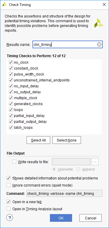
Figure 3: Check Timing command
Designers should know where they have CDC paths in their design and those paths should be documented. The documentation should include:
- Identification of the CDC paths.
- Synchronizing circuits used to cross the CDC paths.
- Reports from Vivado (see later).
- A description of the clock and reset startup sequence for each clock domain.
Xilinx’s Vivado offers a number of ways for finding CDC paths in your design but before using them, you must ensure that all clocks in your design are covered by a timing constraint. To do that, run the check_timing command either from the GUI or from the Tcl command line.
The Clock Interaction Report
Once you have ensured that your timing constraints, especially the clocks, are correct and completely cover the design, you can start searching for CDC paths. One of the easiest and most immediate ways to do this is using the Clock Interaction Report.
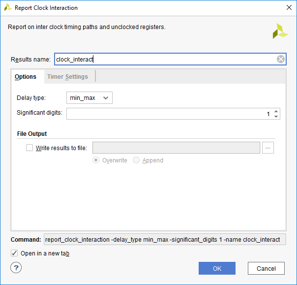
Figure 4: Report Clock Interaction command
This will generate a matrix of the source and destination clocks and the timing relationship of any paths that cross between them:
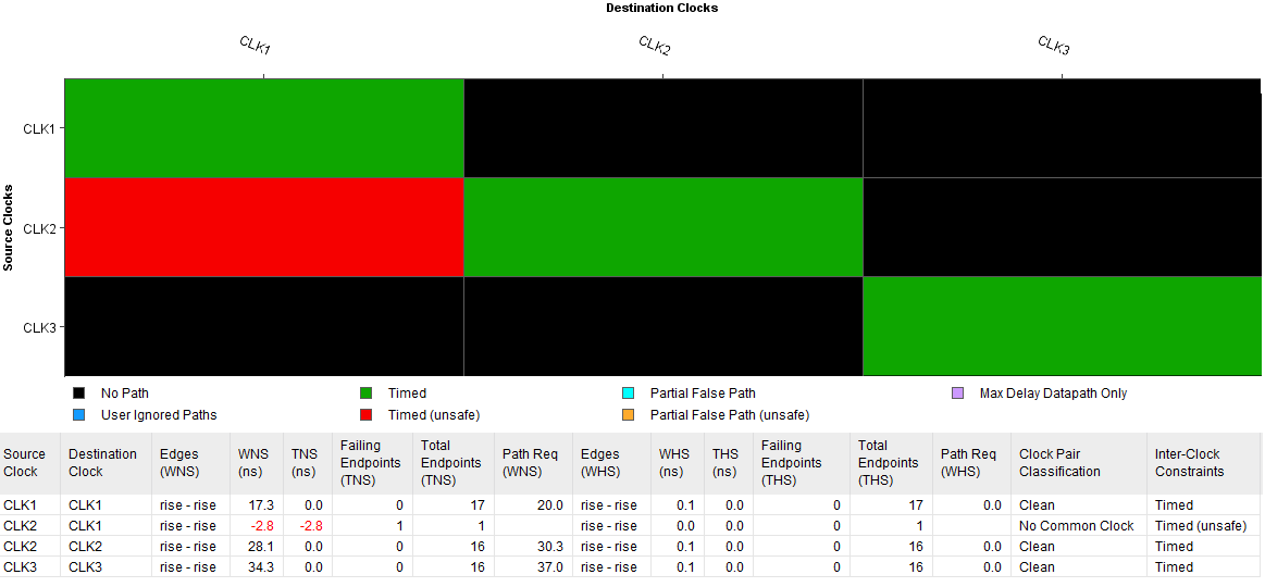
Figure 5: Clock Interaction matrix
In the example in figure 5, we can see that there are three clocks in the design (CLK1, CLK2 and CLK3) and that there are one or more CDC paths that start in CLK2 domain and end in the CLK1 domain.
Report Methodology
Vivado has an extremely sophisticated and rigorous set of methodology checks that can be applied using the Report Methodology command. As we are only searching for CDC paths, it is sufficient to enable just the Timing methodology checks:
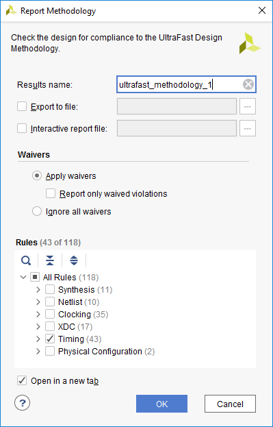
Figure 6: Report Methodology command
If there are any CDC paths in the design, they will be displayed in the Methodology window. The Severity is marked as ‘Warning’, but you should treat these as errors and fix them before going forward.
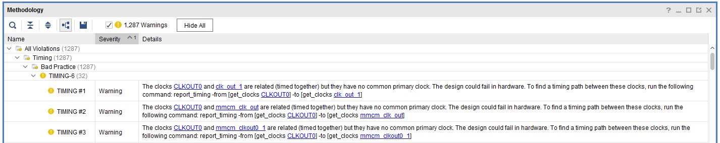
Figure 7: Methodology window showing CDC warnings
The Methodology Warnings themselves don’t identify the exact CDC paths, just the fact that they exist. But they do provide the report timing
commands necessary for finding the paths. If you look carefully at the first Warning in figure 7, you can see that the text suggests
the use of the following command:
- report_timing -from [get_clocks CLKOUT0] -to [get_clocks clk_out_1]
This command will generate a timing report for paths between the two clocks. Add the -name option if you prefer to see the results in
a Timing window rather than as text in the Tcl console. If you create a Timing window, it’s easy to select any path and cross-probe back
to the source code or create the path schematic.
Report CDC
Vivado’s Report CDC command does much more than just find the CDC paths. It will do a full structural analysis of paths between asynchronous clocks and label them as ‘safe’ or ‘unsafe’ according to the kind of clock crossing circuitry that it finds.
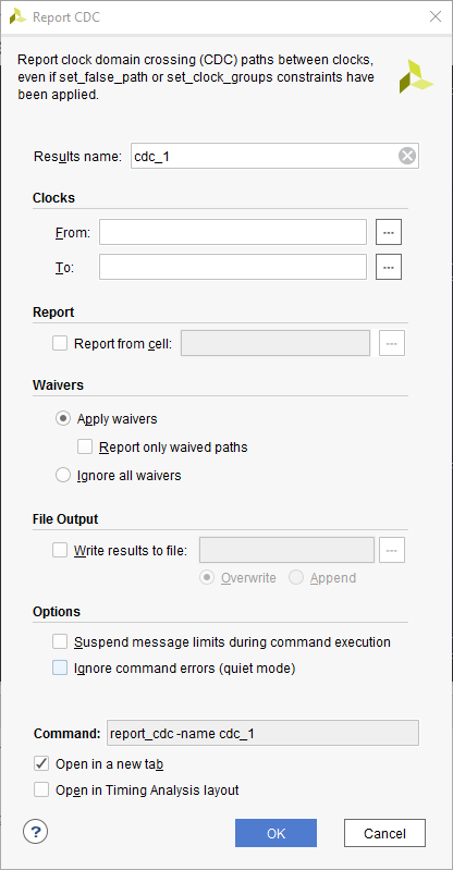
Figure 8: Report CDC command
Now that we know where all the CDC paths are in our design, we can move on to dealing with them − that will be part 2 of this article.