Efficient frequency division with SRLs
One of the most common functions that is implemented inside an FPGA is clock division. For example, faced with having to divide a clock by a factor of 27 the FPGA designer will either use an internal PLL or write a piece of code like this:
- signal counter : unsigned(4 downto 0):= (others => '0');
- signal counterrst : std_logic;
- begin
- -- 5bit up counter
- process (clk)
- begin
- if (clk'event and clk='1') then
- if (counterrst = '1') then
- counter <= (others => '0');
- else
- counter <= counter + 1;
- end if;
- end if;
- end process;
- -- comparator to check when count reaches 25
- process (clk)
- begin
- if (clk'event and clk='1') then
- if (counter = x"19") then
- counterrst <= '1';
- else
- counterrst <= '0';
- end if;
- end if;
- end process;
- divided_clk <= counterrst;
This code certainly works, it produces an active-high pulse every 27 clock cycles which could be used as a clock or, even better, as a clock enable. However it is hardly the most efficient way of doing it. The above code generates a structure like this:
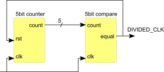
Figure 1: Counter and comparator
A much more efficient way can found by using the SRL32 primitives and initialising such that it contains a single logic '1' with all other bits set to '0'. The address of the SRL32 is set to 26 and it's output feeds back into its input such that the logic '1' circulates round 27 stages:
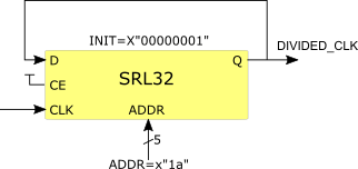
Figure 2: SRL32 configured as 27bit shift register
The VHDL code for inferring this structure looks like this:
- signal shiftreg : std_logic_vector(26 downto 0):= x"000000" & "001";
- process (clk)
- begin
- if (clk'event and clk='1') then
- shiftreg <= shiftreg(25 downto 0) & shiftreg(26);
- end if;
- end process;
- divided_clk <= shiftreg(26);
Synthesis tools such as Vivado will usually create a hardware structure which includes a flip-flop as the final stage of the shift register to improve clock-to-out timing:
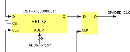
Figure 3: Vivado generated hardware
If required, the SRL32 can be instantiated rather than inferred:
- i_sreg : srlc32e
- generic map (init => x"00000001")
- port map (
- q => feedback,
- q32 => open,
- a0 => '0',
- a1 => '1',
- a2 => '0',
- a3 => '1',
- a4 => '1',
- ce => '1',
- clk => clk,
- d => feedback );
- divided_clk <= feedback;
Generating very slow clocks
Acknowledgement: This section is copied from work by Ken Chapman.
So far we have described an efficient way to produce a clock divider but with limited division factors - up to 32 with a single SRL32. But what if we are required to generate a very slow clock when we have a very fast clock input? Let's take the example of a clock with a one second period (i.e. 1Hz) that must be generated from a 100MHz input. Here we are required to divide by 100,000,000 so if we use the counter-comparator technique, we would need a 27 bit binary counter and a 27 bit comparator. SRL32s come to our rescue again in this case. If you look back to the VHDL code for instantiating an SRL32, you can see that the SRL32 primitive has a clock enable (CE) input — we can use this to create a multi—stage divider that can give much higher division factors. We need to divide by 100,000,000 — if we look carefully we can see that 100,000,000 = 25 x 25 x 20 x 20 x 20 x 20, so what we need is six SRL32s. The first stage is almost identical to the earlier code with a single SRL32 that has a "circulating " pulse that runs round 25 taps of the SRL32. This produces a one clock wide pulse every 25 clock cycles. This signal is used to enable the second stage, which is also an SRL32 with 25 stages and a circulating logic '1'. However, it is enabled only once every 25 clock cycles. The output of this second SRL will be a pulse that is 25 clock cycles long so we require a bit of extra logic to produce a one clock wide pulse. Then all we need to do is daisychain the other four divide—by—20 stages together to make a divide—by—100,000,000 circuit:
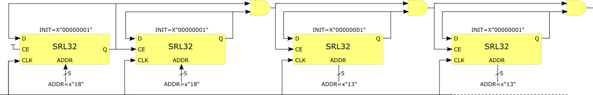
Figure 4: Divide—by—100,000,000
An example of how to code this can be found here. This technique can be used to create frequency dividers for any number that can be factorised into integers less than 32. For example, a division by 255 can be done using just two SRL32s set for lengths of 17 and 15.